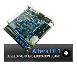
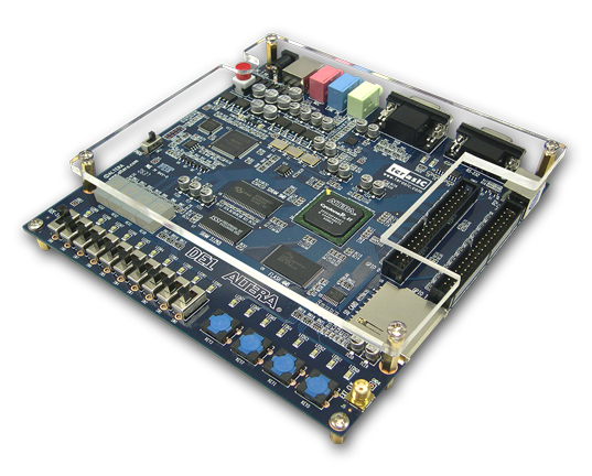
The purpose of Altera DE1board is to provide the ideal vehicle for learning about digital logic, computer organization, and FPGAs. It uses the state-of-the-art technology in both hardware and CAD tools to expose students and professionals to a wide range of topics. With a rich set of features, DE1 board makes it suitable for use in a laboratory environment for university and college courses for a variety of design projects as well as for the development of sophisticated digital systems. Altera also provides a suite of supporting materials for the DE1 board, including tutorials, "ready-to-teach" laboratory exercises, and illustrative demonstrations.
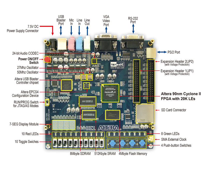
FPGA
Altera Cyclone II EP2C20F484C7 FPGA (20,000 logic elements included)
EPCS4 serial configuration device
I/O Devices
Built-in USB Blaster for FPGA configuration RS-232 port
Traditionally, manufacturers of educational FPGA boards have provided a variety of hardware features and software CAD tools needed to implement designs on these boards, but very little material has been offered that could be used directly for teaching purposes. Altera DE1 board is a significant departure from this trend. In addition to the DE1 board's hardware and software, Altera provides a full set of associated laboratory exercises that can be performed in a laboratory setting for typical courses on logic design and computer organization.
DE1Software provided with the DE1 board features the Quartus II Web Edition CAD system, and the Nios II Embedded Processor. It also includes several aids to help students and professionals experiment with features of the board, such as tutorials and example applications.
Courses on the design of logic circuits and computer organization usually include a laboratory component. In a modern curriculum, the laboratory equipment should not only ideally exemplify state-of-the-art technology and design tools, but also be suitable for exercises that range from simple tasks illustrating fundamental concepts to challenging designs that require knowledge of advanced topics. The DE1 board is designed to be the ideal equipment in all of these cases
University of British Columbia –Introduction to Microcomputers
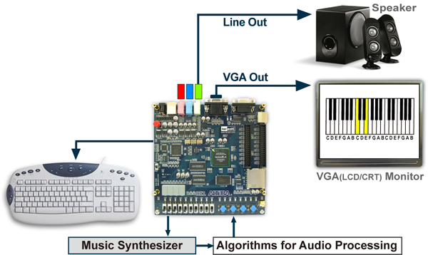
The DE1 board can be used to implement a wide assortment of interesting design projects. A number of examples of advanced circuits implemented on the DE1 board are illustrated below:
Electronic Keyboard
CD quality 24-bit audio
VGA monitor
Ideal platform for audio processing applications
All software driver source code for Nios II included
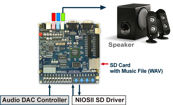
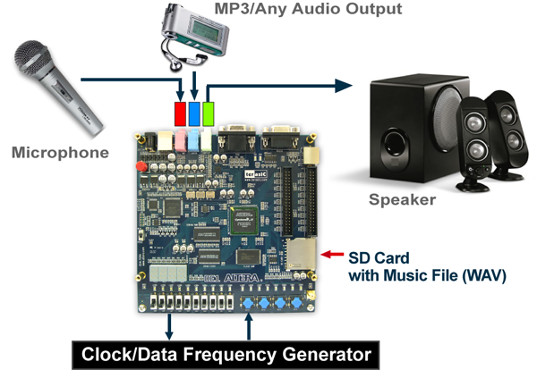
Karaoke Machine and SD Music Player
CD quality 24-bit audio
Ideal platform for audio applications
All software driver source code for Nios II included